CATV equipments · Seehai
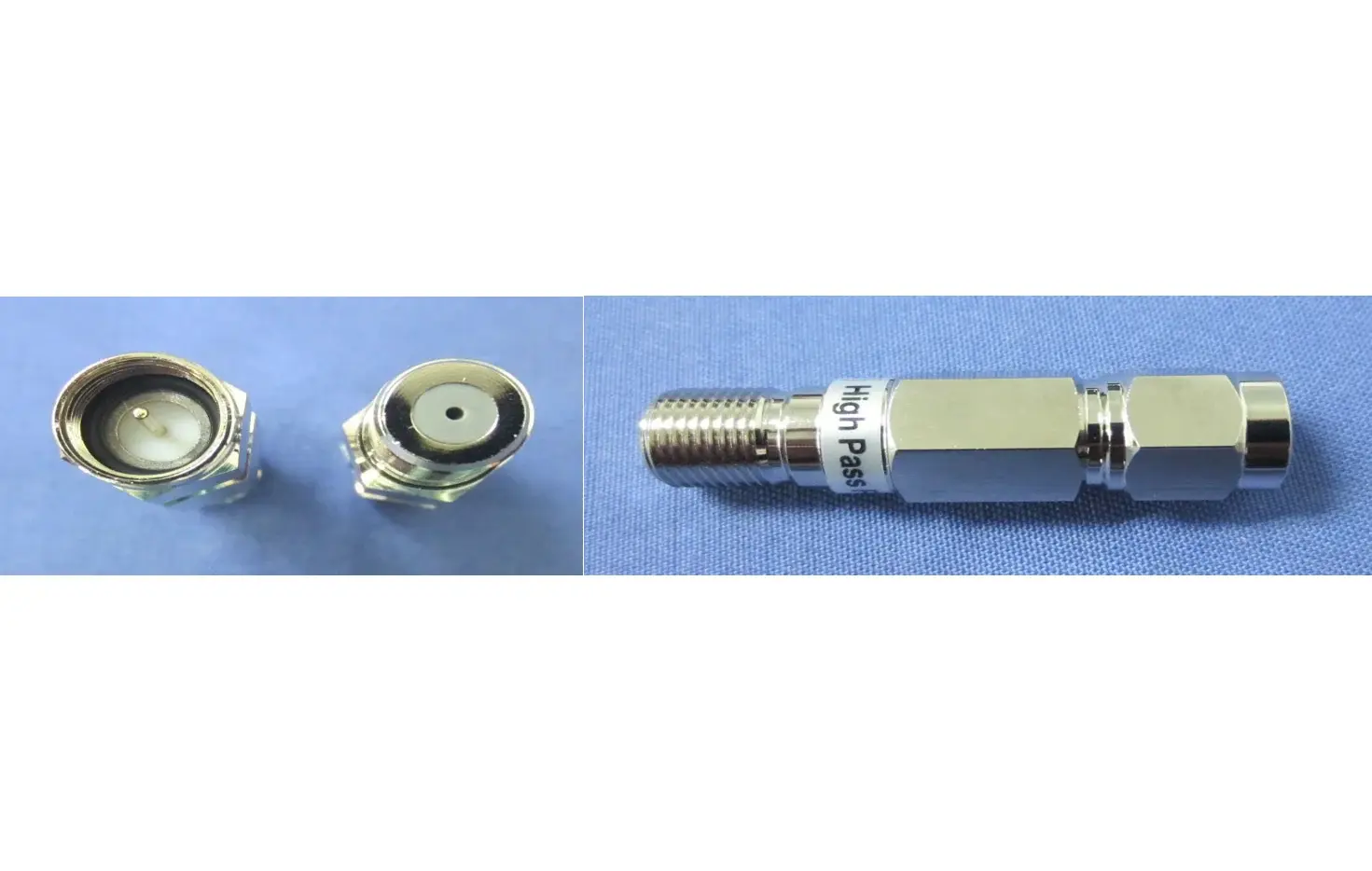
High-Pass Filter
SHPF-6585-FAll-in-one brass structure with nickel-plated surfa Small size fit for indoor use. Can be installed separately, or as…
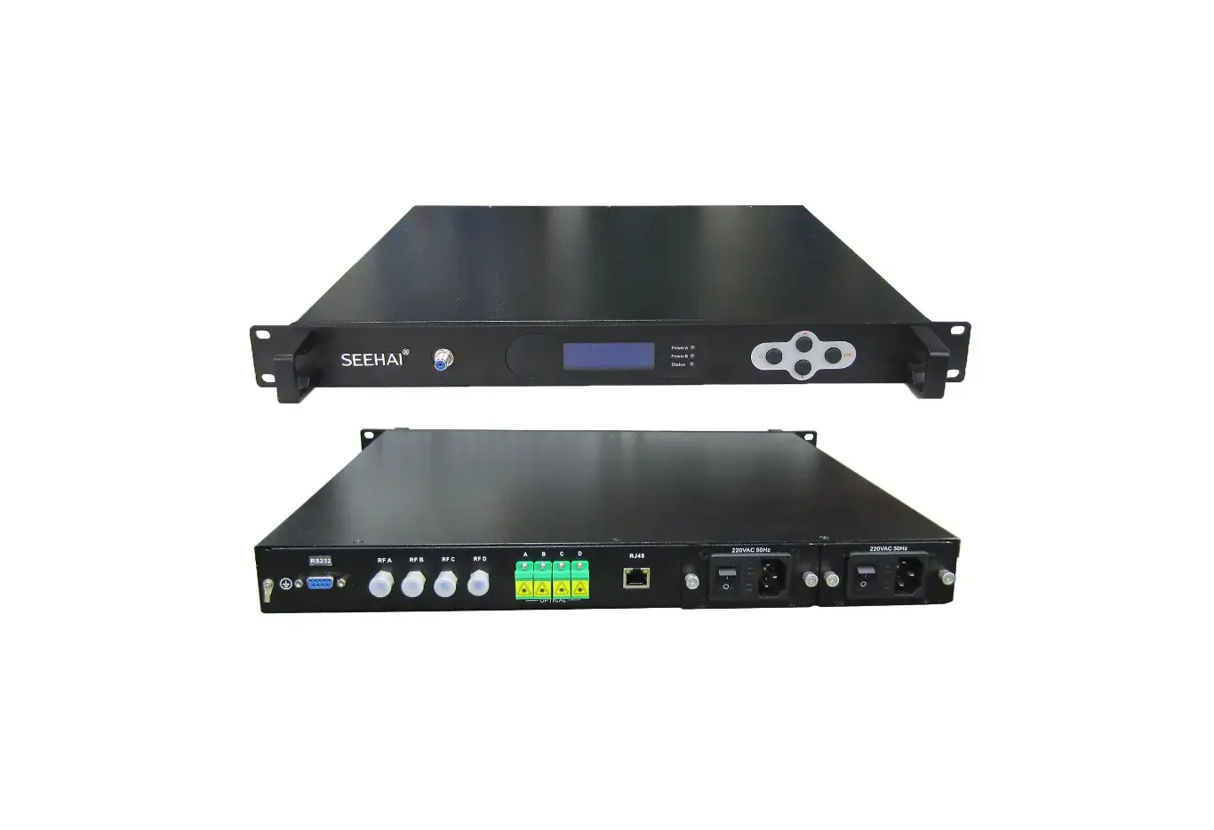
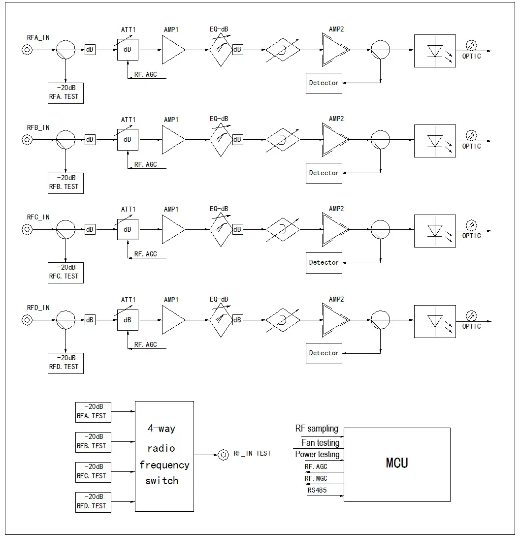
In HFC broadband network, 4 Ports Standalone 1310nm Optical Transmitter can put RF CATV signal to optical modulation through the product's internal four ways coaxial laser, to realize electro-optical conversion and send continuous, stable and reliable four ways 1310nm optical signals.
The front panel of optical transmitter has LCD display and buttons. RF test port, the rear panel has F type British connecting plug and optical output port, convenient for installation and maintenance. The transmitter adopts low power consumption design, reduces heat value and improves product stability. The input level of the transmitter is automatically controlled by the microprocessor (AGC) to achieve the best performance without user adjustment. The level (MGC) can also be manually adjusted to meet specific user requirements.
19 inch 1 U rack mount, standalone.
4 RF signal input individually, 4 optical signal output individually.
RF input level has wider operating range.
AGC/MGC mode optional.
RF level adjustment function.
Stable optical power output.
Front panel has LCD display and control operating parameters.
Adopts one switchable RF monitoring port, users can choose to check each port of RF input level.
Dual power configuration, single power supply can work independently, dual power hot backup mode. Modular power supply design, convenient and fast replacement.
Low power consumption design, low heat value, improved stability.
Standard RJ45 and RS232 Ethernet interface, to monitor operating parameter and report to network management systems.
Through the front panel LED indicator color to provide local alarm indication
The specifications below are taken from the product catalog.
Block Diagram:
SOT S04 6 SC N EN
Block Diagram:
| No. | Item | Unit | Parameter |
| Optical Wavelength | nm | 1310±20 | |
| Optical Output Power | dBm | ≥6 | |
| Laser | DFB from G7/EU countries | ||
| Amplifier type | MMIC from G7/EU countries | ||
| Optical Connector | SC/APC | ||
| RF Input Level | dBuV | 80±5 | |
| Frequency | MHz | 47 ~ 1002 | |
| RF Input impedance | Ω | 75 | |
| RF Input Return Loss | dB | ≥14 | |
| Link Frequency Response | dB | ±1 | |
| RF ATTN Adjustment Range | dB | ≥12 | |
| RF ATTN Adjustment Stepping | dB | ±0.5 | |
| Level Monitor Port | dB | -20±1 | |
| RF AGC Control | dB | ±5 | |
| RF Connector | British | ||
| C/CTB | dB | ≥60 | |
| C/CSO | dB | ≥58 | |
| C/N | dB | ≥48 | |
| Operating Temperature | ℃ | 0℃-+40℃ | |
| Storage Temperature | ℃ | -25℃~+85℃ | |
| Relative Humidity | % | 20-85(non condensing) | |
| Voltage | VAC | 100~240 | |
| Power | W | 15(MAX) | |
| Dimension | mm | 482.6 mm(L)×450mm(W)×44.45mm(H) | |
| Weight | kg | 5 |
Appearance Interface

Accessory of front panel:
| No. | Function |
| 1 | Put the transmitter fix in 1U rack or Slotting thumbscrew of optical transmitting platform. |
| 2 | Handle |
| 3 | RF Test Port- RF Level Test Port |
| 4 | LCD: status and alarm display |
| 5 | Power A: LED indicator, two colors: Green—normal operation, no report and alarm Red —significant error or violation of major alarm limits |
| 6 | Power B: LED indicator, two colors: Green—normal operation, no report and alarm Red —significant error or violation of major alarm limits |
| 7 | Status: LED indicator, two colors: Green—normal operation, no report and alarm Red —significant error or violation of major alarm limits |
| 8 | C Button: Cancel or return |
| 9 | Button:Down |
| 10 | OK Button:Confirm |
| 11 | Button:Up |
Rear Panel

Accessory of rear panel:
| No. | Function |
| 1 | Grounding Screw |
| 2 | RS232 PORT |
| 3 | No |
| 4 | RFA-RF input port |
| 5 | RFB-RF input port |
| 6 | RFC-RF input port |
| 7 | RFD- RF input port |
| 8 | OPTA- Optical output port |
All-in-one brass structure with nickel-plated surfa Small size fit for indoor use. Can be installed separately, or as…
Body is made by high grade aluminum alloy with chromate conversion coating for excellent corrosion resistance . Cable…
Bandwidth: 5 MHz to 1 GHz. Nominal Impedance: 75 Ohms. Insertion Loss : 0.2 dB Max. Return Loss: 28 dB minimum.…
Send a request to get help choosing equipment and a connection plan.