CATV equipments · Seehai
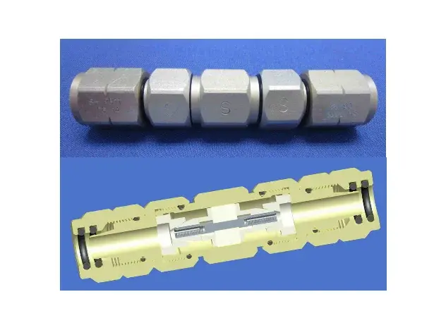
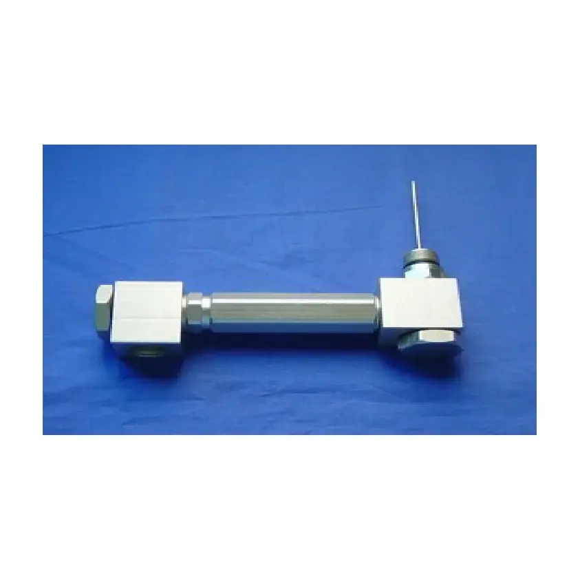
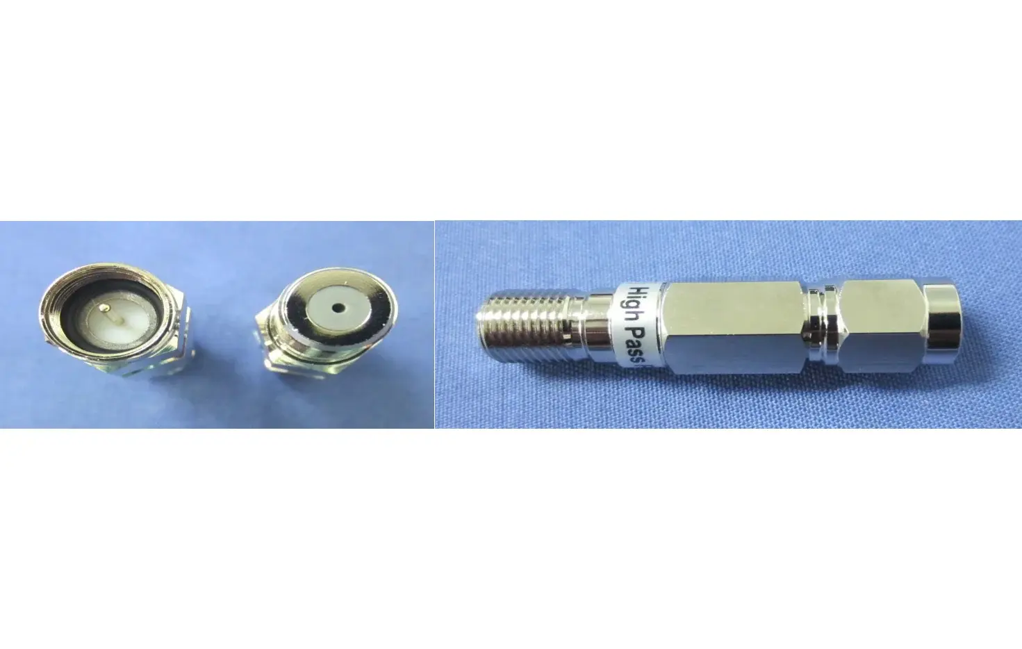
High-Pass Filter
SHPF-6585-FAll-in-one brass structure with nickel-plated surfa Small size fit for indoor use. Can be installed separately, or as…
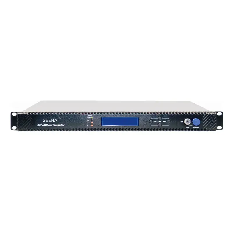
According to the Next Generation Broadcasting (NGB) planning and PON standards, 1550nm is defined as the transmission wavelength for HFC downstream. The high cost of 1550nm external modulated transmitter and dispersion effects of 1550nm directly modulated make network transformation difficult. Thus we create the 1550nm directly modulated optical transmitter with electronically controlled dispersion compensation. It supports up to 1.2GHz band and DOCSIS 3.1 system. With two RF inputs and high isolation, it enables the signal transmission of QAM and IPQAM smoothly. Support a transmission distance of 50KM with electronically controlled dispersion compensation. Built-in CWDM is optional for multi-wavelength networking.
870/1003/1218Mhz band, support DOCSIS 3.1 system.
The AGC and MGC gain control modes are optional.
Dual power supply; hot backup; a variety of power supply options are available, optional AC220V and DC48V.
Laser output power, bias current and cooling current are detected in real time.
Optional CWDM for optical signal insertion.
Electronically controlled dispersion compensation can support a transmission distance of 50KM.
Low-cost solution is comparable to the performance of external modulated transmitter.
ITU standard wavelength is optional.
The specifications below are taken from the product catalog.
Schematic diagram
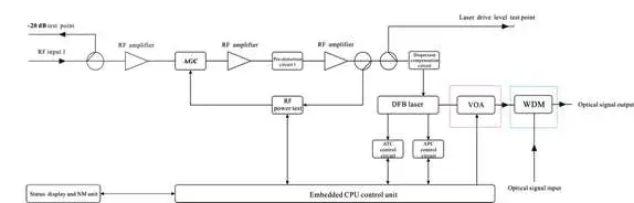
Diagram of 1550nm_Directly_Modulated_Optical_Transmitter.png
Note: The optical attenuator in the red dashed box and the wavelength division multiplexer in the blue dashed box are optional.
Specifications
| Item | Unit | Parameter | |
| Optical Part | |||
| Optical wavelength | nm | ITU wavelength | |
| Laser type | Butterfly-typed DFB laser | ||
| Optical modulation mode | Direct optical intensity modulation | ||
| Optical connector type | FC/APC or SC/APC | ||
| Output optical power | mW | 10 | The insertion loss of the VOA and CWDM is excluded. |
| External optical signal input | dBm | -5~10 | |
| RF Part | |||
| Frequency range | MHz | 47~870/1003/1218 | |
| RF input level | dBuV | 77± 5 | |
| Flatness in band | dB | ± 0.75 | |
| Input return loss | dB | ≥ 16 | |
| RF AGC control range | dB | ±5 | |
| RF MGC adjustable range | dB | 0~20 | |
| RF input isolation | dB | ≥ 50 | Isolation between two RF inputs |
| RF input test port | dB | -20±1 | |
| Laser drive level test port | dB | -20±1 | |
| Electronically controlled optical attenuator tolerance | dB | ≤1: ATT 0-15dB | |
| ≤3: ATT 16-20dB | |||
| CNR | dB | ≥ 48 | 550MHZ 59CH analog signal 77dBuV/CH |
| C/CSO | dB | ≥ 58 | 550-870MHZ 40CH digital signal 67dBuV/CH |
| C/CTB | dB | ≥ 63 | 25 Km, -1dBm input |
| CNR | dB | ≥ 46 | 550MHZ 59CH analog signal 77dBuV/CH |
| C/CSO | dB | ≥ 55 | 550-870MHZ 40CH digital signal 67dBuV/CH |
| C/CTB | dB | ≥ 63 | 50Km, -1dBm input |
| MER | dB | ≥ 40 | 25 Km, -1dBm input, 96CH digital 77dBuV/CH |
| ≥ 39 | 50 Km, -1dBm input, 96CH digital 77dBuV/CH | ||
| Others | |||
| Maximum power consumption | W | ≤10 | |
| Operating temperature | ℃ | -5 ~ + 55 | |
| Storage temperature | ℃ | -30 ~ + 70 | |
| Weight | Kg | 5.5 |
Structure Description

Structure Description of 1550nm Directly Modulated Optical Transmitter
Front panel
| 1 | Power indicator |
| 2 | Device running indicator: This indicator will flash by 1Hz frequency after the device start running normally. |
| 3 | Laser working status indicator: Steady green light: The laser is operating normally. Steady red light: The laser is not turned on. Blinking red light: The device has a parameter alarm. You can view the alarm in the Alarm Status, the second level submenu. |
| 4 | Laser drive level indicator: Steady green light: Drive level is normal. Blinking red light: Drive level alarm. You can view the alarm in the Alarm Status, the second level submenu. |
| 5 | 160×32 dot-matrix LCD screen: used to display all the parameters of the machine. |
| 6 | Display the exit or cancel key of the setup menu. |
| 7 | Display the up or increase key of the setup menu. |
| 8 | Display the down or decrease key of the setup menu. |
| 9 | Display the enter key of the setup menu. |
| 10 | Laser switch: ON: The laser is on. OFF: The laser is off. Keep the laser off before the device is powered on, and turn on the laser after the self-inspection is completed when power on. |
| 11 | Laser drive level test port: -20dB |
1550nm_Directly_Modulated_Optical_Transmitter_4.png
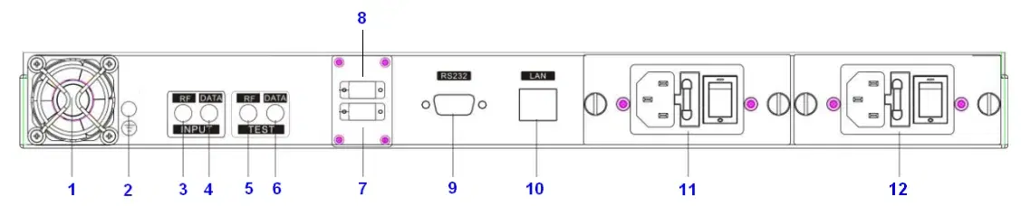
Rear panel
| 1 | Fan | 7 | Optical signal output |
| 2 | Ground stud, ensure good grounding before power on | 8 | Optical signal input: without WDM, no this port |
| 3 | RF input 1 | 9 | RS232 interface |
| 4 | RF input 2 | 10 | LAN interface |
| 5 | RF input 1 test port -20dB | 11 | Power module 1, hot swappable |
All-in-one brass structure with nickel-plated surfa Small size fit for indoor use. Can be installed separately, or as…
Body is made by high grade aluminum alloy with chromate conversion coating for excellent corrosion resistance . Cable…
Bandwidth: 5 MHz to 1 GHz. Nominal Impedance: 75 Ohms. Insertion Loss : 0.2 dB Max. Return Loss: 28 dB minimum.…
Send a request to get help choosing equipment and a connection plan.